

- By Bill Hollifield
- InTech
Summary
Alarm management's powerful infrastructure extends to many other important uses
By Bill Hollifield

We know that although thousands of alarm systems still remain unaddressed, only the will to improve them is needed. No "new knowledge" is required, no reinventing of the wheel is needed, and no magic breakthrough is going to fix a suboptimal alarm system with zero effort. Yes, organizations are still making improvements in technique and software, such as reducing nuisance alarms by fully automating alarm delay time analysis to provide the optimal settings. But this is an enhancement, not a fundamental change in the necessary work process.
So, where is "alarm management" going? Once you have accomplished alarm system improvement, what is next? Can you leverage the software and work processes in place for alarm management to achieve other significant improvements? Many companies are doing exactly that.
Infrastructure of alarm management
With good reason, alarm management has expanded into being an integrated part of many companies' "operational excellence" programs. These initiatives include corporate performance dashboards, risk tracking, "operational intelligence," and similar terms sometimes grouped under the category of "Industrie 4.0." Alarm system performance was an obvious early choice for inclusion in any kind of key performance indicator (KPI) dashboard that included safety.
In accomplishing this, the underlying technology of alarm management has also been adapted to other uses that often have little to do with alarms. The reason? When engineers are given a flexible and powerful capability, we immediately figure out other things we can do with it. And the infrastructure used to accomplish alarm management is powerful indeed. It has the following capabilities.
Connectivity: Alarm performance monitoring requires a safe, secure connection to the control system. The most popular, automated methods of such monitoring use a dedicated server that listens to the alarm and event traffic in the control system. These events are copied into a separate database. They are analyzed automatically, and reports are generated. Operator changes and control system changes are usually also stored.
OPC is commonly used as the connection method, and it brings the ability to read other information in the control system, such as current process values, equipment states, and even the point configuration settings of alarms, controllers, modes, and tuning coefficients-pretty much anything on the system.
With this data available, it becomes easier to perform basic analysis of control loop performance. For example, engineers can identify loops not operating as designed and other control strategy improvement opportunities (e.g., controller loops with the most frequent set point or mode changes, or loops that spend the most time in manual mode). While this is short of a fully featured control loop performance monitoring software solution, it is a great tool for getting started.
Master alarm database (MADB): An MADB is essential to alarm management. It is a controlled, evergreen list of all alarms and details about them. The information can be quite substantial, containing multiple alarm causes, consequences, corrective actions (both console operator and outside operator actions), reasons for set point, allowable response time, indication an alarm is taken as an independent protection layer (IPL), and alarm classification in compliance with ISA-18.2.
It is common to give operators a tool that lets them have read access to this useful information. It is even better to give access to the information from within a process control graphic, but that is for a different discussion of high-performance human-machine interface (HMI).
Because alarm management requires ongoing verification that alarms have not undergone any unauthorized change, it is common to run a periodic automated check, called an audit. The alarm server reads the settings of each alarm, compares them to the MADB, and generates reports on any mismatches. Because any authorized change to an alarm should have followed management-of-change (MOC) practices and updated the MADB, a mismatch detects either an unauthorized change or a failure to follow MOC procedures.
OPC has both read and write capability, so some companies apply both audit and enforcement, where certain important alarms have an immediate write-back correction and automated management notification if they have been improperly changed.
Computation: The software running on the alarm management (AM) server is often quite sophisticated and provides for advanced real-time techniques, such as state-based alarming, alarm shelving, and independent operator-controlled alert systems.
For example, in state-based alarming, the alarm server continuously monitors certain process conditions, uses logic to determine a process state change, and then alters the online alarm settings to match the new state in a predefined way. A change in feedstock or product may require some alarm settings and priorities to change for optimal performance. An equipment trip can generate dozens of nuisance alarms, but a state-based solution can detect such a trip and suppress those alarms.
These functions are usually far easier to achieve via a good alarm management solution than by attempting to code them into the underlying control system configuration. In accomplishing these and similar alarm functions, the alarm server has become a real-time decision-making addition to the control system.
Beyond alarm management
This combination of process connectivity, the MADB, and computational capability is a powerful one that opens significant opportunities for improvement. Automation engineers in forward-looking corporations are now using these capabilities to do much more than alarm management. Two such applications are called boundary management and independent protection layer monitoring.
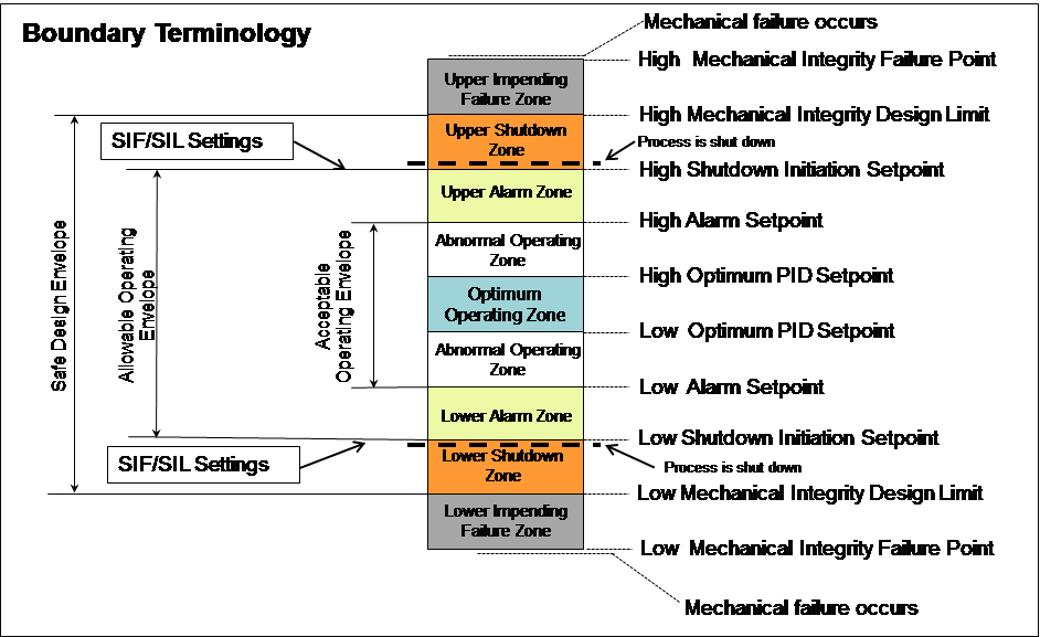
Boundary management
Boundary management is the continuous computation, indication, and reporting of the process's position within both safe and optimal operating envelopes. The important safety, efficiency, and quality boundaries of a process are typically stored in a hodgepodge of different procedures and documents. These are often contradictory, out-of-date, or even lost. Control system interlock settings, for instance, may not match the correct design documents.
A one-time effort identifies and places all the correct data into a new section of the controlled MADB. Sources of the data include process design documents, piping and instrumentation drawings, equipment specifications, process hazard analyses, operating procedures, and other similar engineering documentation.
Once the documentation is in place, continuous monitoring via the AM server (or a connection to a process historian) feeds real-time analysis, depiction, and reporting of significant boundary information. The kinds of reports that are useful include:
- most frequent boundary excursions
- time in excursion
- excursions per processing unit and boundary type
- excursions ranked by importance and time
- automatically calculated financial losses per excursion
This technology also allows engineers to monitor process or equipment conditions to see when they are approaching or outside the optimal zones. The proximity of the process to quality, safety, or environmental boundaries can be depicted in real time, used to generate warning messages, and summarized in automated daily or weekly reports. It has never been easier for engineering and corporate management to understand what is really happening in the plant. This can have a profound, positive effect on safety and production.
Independent protection layer monitoring
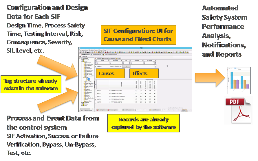
Companies install independent safety instrumented systems (SIS) incorporating safety instrumented functions (SIF) to mitigate process risks. A SIF acts as one IPL against a specific process hazard. The information regarding SIF design values is usually in a variety of uncontrolled, disparate documents. Like process boundaries, there is often not a "single source of the truth." The many different operating and maintenance procedures referring to the SIFs and the SIS have the potential for inconsistency with their design. For example, an operating procedure may mention one set point for SIF activation, while a SIF design document specifies a different one, and a maintenance test procedure in the work order generation system has another-it is common for disparate systems to accumulate errors.
Because SIS management has the potential for errors, inconsistencies, and wasted effort, a controlled and automated solution is desirable. Again, a new section of the MADB is used to consolidate the correct settings for all SIFs, which are then monitored. Changes are automatically reported to ensure proper MOC. But, we can go beyond that to achieve better performance and even cost savings.
Living with a SIS: Once designed and in operation, there are many administrative tasks associated with a SIS. These include performance monitoring, maintenance, SIF bypassing, change management, periodic proof testing, and ongoing suitability verification. These tasks require the attention, time, and effort of engineers and technicians. Plants report that these tasks are accomplished using a variety of inconsistent, error-prone, and potentially unreliable methods. These include uncontrolled spreadsheets, notes, homegrown applications, and manually marked-up drawings and sketches. There is often no organized method applicable to similar SISs at different sites. Automation can make a major improvement by accomplishing all these tasks in a combined solution called IPL monitoring.
SIF bypass management: One of the most important tasks is bypass management. A safety function must be capable of being fully or partially bypassed. There are many different methods to accomplish this, but they require rigorous control. Bypass design is usually for testing or, in some cases, for special operating modes such as startup. Bypassing a particular SIF introduces additional risk during operation. Special interim procedures may be required during a bypass. It is essential that a bypass is not missed or forgotten, and yet such things have occurred.
The state of all SIF bypasses should be automatically monitored and made easily visible to operators and staff. (Operators normally have alarms to indicate a bypass condition.) Detailed reports on all SIS bypasses, such as their frequency and duration, should be automatically created.
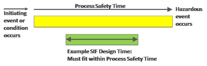
SIF design calculations: SIF demand rates and response times were assumed in the design phase. These assumptions are supposed to be verified by actual performance numbers once in service. This is a task that is often overlooked in the aftermath of whatever event caused SIF activation. But, if the demand rate assumption is wrong, the SIF may need to be redesigned (to provide the needed safety level), or it may be overly designed, overly complex, and scheduled for testing more often than needed. If the response time was calculated incorrectly, the safety function may be compromised. The solution is to calculate and track demand and response rates automatically for all SIFs, for performance and design verification. Full reporting of various KPIs related to the entire safety instrumented system can be totally automated.
SIF testing: It is mandatory in both the standards and in regulations to periodically test SIFs, including the inputs, logic, and outputs. The frequency of testing is determined in part by the design assumptions, such as demand rate. Testing is expensive, in terms of both technician costs and lost production.
Many organizations wait until a scheduled outage for SIF testing-which increases outage duration and lost production. This practice also consumes technical and maintenance resources during turnarounds, potentially delaying other tasks.
Some SIFs are tested online. There is a risk of full SIF activation during online testing. Additionally, this practice is often accompanied by reduced rate operation, and hence lost production. It is therefore desirable to not test more often than necessary. Feedback of the actual demand rate compared to the assumed rate in design can often lengthen the test interval.
Cost savings in SIF testing: The documentation of every SIF activation, with time-stamped records of all the components involved, can be automated. Trip occurrence can then be taken as a partial or full credit for a test. If partial, the scope of the next test may be reduced, saving time and effort. If full, the next testing date can therefore be reset based on the last actual SIF activation. This can be done via automated connectivity to the maintenance scheduling system, and the cost and impact of SIF proof testing can be significantly reduced.
Visualization of risk:
Risk is increased when a SIS is bypassed, when testing is occurring or overdue, and when other IPLs (such as the control loop in the basic process control system, redundant instruments, or certain alarms) are unavailable. Historically, it has been impractical, or even impossible, to determine the current real-time risk level of a process as a result of one or more IPLs being out of service. Should these conditions occur simultaneously, the plant may then be operating in a significantly higher risk condition than was ever intended. In such conditions, the familiar safety model showing that "the holes in the slices of swiss cheese are lining up" is applicable, and accidents are more likely to occur.
The AM infrastructure can be used to monitor the status of various IPLs automatically. When any of the IPLs are unavailable, out of service, overdue, bypassed, or otherwise compromised, the current risk profile can display on a dashboard, appear in automatic reporting, and generate immediate notifications.
Maximizing alarm management
We engineers are all about efficiency. It is in our nature to maximize the use of a powerful capability. Boundary management and IPL monitoring are examples of using the alarm management infrastructure as part of an overall operational excellence initiative. These applications have proven effective and are gaining widespread adoption. More ideas are surfacing and taking us far beyond alarm management.
Reader Feedback
We want to hear from you! Please send us your comments and questions about this topic to InTechmagazine@isa.org.