

- By Katherine Bartels, Adam Harmon
Summary
Choked flow is a poorly understood phenomenon that can affect control valve sizing, along with trim and material specification.

This article describes the phenomenon of choked flow and shows why it occurs and how it can be predicted. It also explains when choked flow conditions are damaging and how this damage can be reduced or avoided.
What is choked flow?
If the inlet pressure (P1) and valve flow area are fixed, the flow through a valve will normally rise as the downstream pressure (P2) is reduced. The “Ideal” line in figure 1 illustrates this point, showing how liquid flow rises linearly when charted against the square root of the differential pressure across the valve divided by specific gravity.
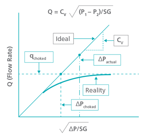
In actuality, the maximum liquid flow through the valve can never exceed a choked flow limit, and at this point flow will increase no further, no matter how low the P2 pressure is reduced.
A similar phenomenon occurs with valves in gas service. If the P1 pressure and flow area remain fixed, flow through the valve will rise as P2 is reduced, but at some point, choking will begin to occur and the flow will rise no higher, regardless of the value of P2.
Why does choked flow occur?
In liquid applications, choking is a result of the reduction in pressure through the control elements. Figure 2 shows the instantaneous pressure as liquid moves through a control valve. The inlet and outlet cross-sectional areas of a valve are much larger than the control area, such as the cage or the area around the plug and seat. Because the total flow at any location in the valve is the same, the liquid velocity in the reduced area (vena contracta) must be much higher to pass the same flow.
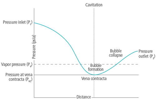
By Bernoulli’s law, the total energy at every point in the flow stream is constant, so if velocity is increased, pressure must fall. As the fluid passes through the restriction, it speeds up, lowering the pressure at that point. Once the liquid enters the much larger outlet piping, the flow rate slows, and some pressure is recovered. This pronounced pressure dip becomes more dramatic as flows are increased.
If the instantaneous pressure in the vena contracta falls below the vapor pressure, then vapor bubbles will begin to form as the liquid begins to boil. The conversion to vapor increases the volume of the fluid and begins to restrict flow. If the downstream pressure is lowered still further, the vapor volume will increase to the point that flow throughput can increase no further, regardless of how low the downstream pressure is reduced. This condition is called choked flow.
In gas applications, the vapor velocity through the valve will increase until the vapor reaches sonic velocity. At this point, the vapor can go no faster because a standing shock wave forms and limits flow. Further reduction of the downstream pressure will have no effect on flow through the valve.
Choked vapor flow conditions are very common in relief valves and control valves with very high flows, but can also occur in high velocity flare headers at piping transitions. Choked flow is also common in vacuum systems, because the low air pressures found in these systems greatly reduce the speed of sound, increasing the likelihood of standing shock waves.
Choked flow misconceptions and issues
Choked flow by itself does not generally damage a valve, but there are flow conditions commonly associated with choked flow that can create problems, including:
Noise levels: Choked flow does not directly create noise, but high noise can result from process phenomena normally associated with choked flow. In liquid systems, cavitation can be present during choked flow, which creates noise and can ultimately damage the valve. As downstream pressure is reduced, cavitation transitions to flashing. While cavitation can have a high sound pressure level due to the implosion of the collapsing vapor bubbles from micro-jets and shock waves, flashing will have reduced noise due to the resulting two-phase flow.
In vapor flow, noise will rise significantly as the velocity turns sonic. As the downstream pressure is reduced, the extra energy is converted to sound energy. Valves with excessive pressure drop can generate sound levels greater than 100 dB.
With either liquid or vapor flows, the overall level of noise is usually related to the differential pressure across the valve. When choking first appears, noise will be present but may not be excessive. As the downstream pressure falls, noise will increase dramatically and can damage valve internals and subject operators to unsafe sound levels.
Flashing and cavitation: A common misconception is that choked flow conditions require flashing conditions, but choked flow can occur under cavitating conditions as well. As shown in figure 2, cavitation will result when the P2 pressure rises above the vapor pressure of the liquid. When this occurs, the bubbles collapse and turn back into liquid. If the P2 pressure remains below the vapor pressure, the liquid will boil and flash to vapor as it passes through the valve and remain a vapor as it exits (figure 3). 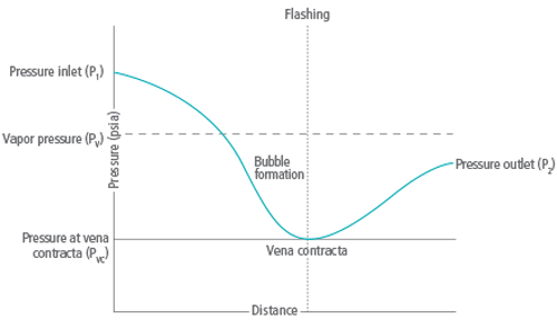
Incipient cavitation will not usually result in fully choked flow. However, as cavitation becomes more pronounced, the flow will begin to choke, and the overall flow will deviate from the ideal flow curve as shown in figure 1. The level of cavitation (and extent of choking) is dependent on the properties of the liquid; the process pressure, temperature, and flow; the inlet and outlet piping; and the specific construction and parameters associated with the valve itself.
Flashing may or may not indicate choked flow. If the valve differential pressure is high, the P2 pressure is well below the vapor pressure, and the flow is low, the flow through a valve could be flashing but not choked.
Valve damage due to choking: Users often assume choked flow conditions will damage the valve. However, there are times when a valve is choked and the damage is minimal, and there are times when the valve is not choked and the rate of damage is significant.
Cavitation can ultimately damage a valve. As the bubbles collapse, they form microjets and create localized shock waves that erode valve internals and downstream piping. As discussed above, cavitation can occur without necessarily fully choking the valve flow.
Flashing conditions can create valve damage as well, but this is typically less pronounced than cavitation damage, and is usually worse at very low valve openings when the valve flow is probably not choked. As the valve opens further, the flow may become choked, but the valve damage will likely be reduced as the plug moves away from the seat. 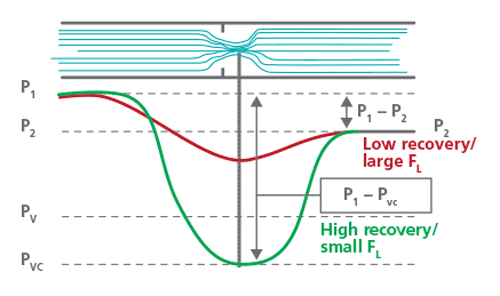
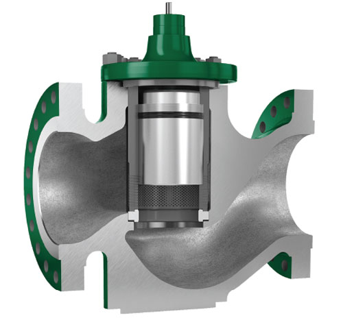
Excessive noise can also damage the valve due to high vibration and metal fatigue. As discussed earlier, the amount of noise generated varies significantly based on process conditions, so the noise may not be directly associated with flow choking. Cavitation, flashing, and noise damage can be alleviated and even eliminated by specifying appropriate valve body designs, special valve trims, and materials of construction (figures 4 and 5).
Low recovery valves (such as globe valves) generate a much less pronounced pressure dip as the flow passes through, so cavitation is reduced. Special anticavitation trims (figure 5) can reduce the risk of cavitation damage even more by either further minimizing the pressure dip, or by directing the cavitating liquid into the center of the flow passage to minimize damage to the valve internals and walls.
Hardened alloys can be used for critical valve internal components to reduce damage caused by flashing or cavitation. Noise can be significantly reduced by using low noise trims, inlet and outlet noise attenuators, or downstream modal noise attenuators.
Valve sizing: Calculating a choked flow scenario is based upon process conditions and flowing media parameters for a given valve position. The fact that a valve is choked for a unique combination of parameters does not mean it cannot pass more flow, as an increase in flow can often be obtained by increasing the Cv of the valve. Software programs are available to predict choked flow conditions and estimate the maximum flow, as described in the subsequent section.
Predicting choked flow
Many valve vendors have control valve sizing programs that can predict choked flow conditions and help users size the valve correctly. However, these programs are only as accurate as the input data, so the correct process and valve information must be entered.
The presence and extent of flow choking depends on many process conditions, including the physical properties of the fluid involved, flow rates, upstream and downstream pressures, process temperature, and inlet and outlet piping configurations—as well as a number of details associated with the control valve itself. Special parameters, such as pressure drop ratio, pressure recovery factor, and cavitation index, help predict exactly when cavitation or choking will occur, and how much flow a valve will pass. Because the parameters for each body style and trim are different, each option must be evaluated individually to determine the actual flow that can be safely passed under a specific set of process conditions.
Such sizing calculations can become complicated, especially when several trim options are available, so it is wise to consult your valve vendor to help evaluate options and determine the best solution for your application.
Valve selection
Choked flow, in and of itself, is not a cause for concern. The confusion stems from the association of choked flow with many negative phenomena that can affect and damage control valves. When faced with the possibility of choked flow, or if there are concerns or questions about how to proceed with valve sizing or selection, contact valve vendors for technical support. They can usually provide valve sizing programs that predict when choking will occur and its impact on valve sizing and selection. They can also help users choose the best combination of materials and trim designs to alleviate damaging conditions.
Reader Feedback
We want to hear from you! Please send us your comments and questions about this topic to InTechmagazine@isa.org.