

- By Charles Fialkowski, CFSE, Luis Garcia, CFSE, Nicholas P. Sands, PE, CAP
- InTech
Summary
Fast Forward
- When implementing ANSI/ISA-18.2, Management of Alarm Systems for the Process Industries, engineers should consider all alarms, including basic process control, safety instrumented systems, fire and gas systems, and emergency response systems.
- In the ANSI/ISA-84.91.01 standard, the term safety alarm is recognized as an element of process safety, and it may be the same alarm covered in the ANSI/ISA-18.2 standard so which standard applies and why?
- How much risk-reduction credit could one take for a safety alarm?
 How much risk can they reduce?
By Charles Fialkowski, CFSE, Luis Garcia, CFSE, and Nicholas P. Sands, PE, CAP
ISA defines an alarm as an audible or visible means of indicating to the operator an equipment malfunction, process deviation, or abnormal condition requiring a timely response. A safety alarm is essentially the same thing, but with the added metric of performance, or in layman's terms, how much risk can it reduce? Risk reduction is generally measured in orders of magnitude (10, 100, 1000, etc.) If a company's process hazard analysis (PHA) identifies and estimates a specific process hazard may be present every 10,000 years, yet there is a target of 100,000 year, it is easy to understand the company needs to reduce the risk by one order of magnitude (10) to reach this target. In general, it is a good practice for plant owners and operators to rigorously identify all potential risk-reduction layers to lessen the burden placed on their dedicated safety instrumented systems (SISs). The industry has been struggling with alarm management issues for decades, but adding the ability to quantify the amount of risk reduction is introducing additional challenges.
The newly revised ANSI/ISA-18.2-2016, Management of Alarm Systems for the Process Industries, states in its scope that the standard specifies general principles and processes for the life-cycle management of alarm systems based on programmable electronic controller and computer-based human-machine interface (HMI) technology for facilities in the process industries.
It covers all alarms presented to the operator through the control system, which includes alarms from the basic process control systems, annunciator panels, packaged systems (e.g., fire and gas systems, and emergency response systems), and safety instrumented systems. It provides a framework for the successful design, implementation, operation, and management of alarm systems in a process plant.

In addition, ANSI/ISA-84.91.01, Identification and Mechanical Integrity of Safety Controls, Alarms, and Interlocks in the Process Industry, was released in September 2012, with the intent of establishing a procedure to identify the process safety functions that utilize instrumentation to maintain safe operation in the process industry. In this standard, these functions are implemented by safety controls, alarms, and interlocks.
The scope of this latter standard is to address instrumentation classified as process safety safeguards by the authority having jurisdiction (typically the owner/operator or local regulatory agency) and to establish requirements for its mechanical integrity, including inspection and testing and documenting the inspection/test results. It is specific to process safety. As illustrated in figure 1 from the ANSI/ISA-84.91.01 standard, the term safety alarm is recognized as an element of process safety, and in many cases, it may be the same alarm that is also covered in the ANSI/ISA-18.2 standard so which standard would apply and why?
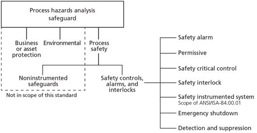
Figure 1. Safety controls, alarms, and interlocks relationship to the PHA
A process alarm may be categorized as safety control alarms and interlocks (SCAI), as defined in the ANSI/ISA-84.91.01 standard. This diagram was important to help identify all the different safeguards that might be claimed by the owner/operator as a layer to reduce risk. These safeguards must be identified during the PHA of the process.
Alternatively, ANSI/ISA-18.2 defines a safety alarm as an alarm that is classified as critical to process safety or the protection of human life. Safety alarms are placed in a highly managed alarm class that have additional requirements throughout the standard.
Furthermore, the scope of the standard clearly indicates that alarm systems serve to notify operators of abnormal process conditions or equipment malfunctions. It may include both the basic process control system (BPCS) and the SIS, each of which uses process conditions and logic to generate alarms.
Therefore, a safety alarm is an alarm as per ANSI/ISA-18.2 that can be considered a SCAI as per ANSI/ISA-84.91.01.
The next question is, how much risk-reduction credit could one take for a safety alarm? Are there limits to the amount one could claim for the operator being able to step in during a critical process situation and effectively bring the process back to a safe state? Imagine a situation where a process hazard event occurred and was not originated by the BPCS. As a result, designers and reliability engineers decided to take one order of magnitude (10) risk-reduction credit for their BPCS. Also, because they identified another independent set of sensors connected to the BPCS, for alarming that same condition, they all agreed to claim another order of magnitude (10) risk reduction. Thus between its basic process control function and its alarm function, the BPCS is now providing two order-of-magnitude (100) risk-reduction credits. Could this be considered a good practice?
Sure, designers could try to argue that the BPCS they are using provides robust technology that includes independent and diverse operations to maintain their claim that two orders of risk-reduction credit would be justified. But we also must consider the human element that resides within this protection layer and that two orders of magnitude (100) in this case might be the recommended maximum limit in the amount of credit taken.
One might also argue that if the safety alarm was connected to separate and independent sensors, had a dedicated HMI alarm panel, and was programmed with a safety certified safety control system capable of meeting safety integrity level 3 (SIL 3)\, they could justify taking even more risk-reduction credits. Yet many designers, with reason, do not feel comfortable with this approach. It has been the center of ongoing debates about where we draw the line on overstretching the claims of safety alarm performance.
Considering that most process safeguards are dormant - in the sense that they would react only when predetermined process hazard conditions are present, it is the owner/operators' responsibility to ensure that their performance is available at all times. IEC 61511-1, second edition, Functional safety - Safety instrumented systems for the process industry, gives requirements for the specification, design, installation, operation, and maintenance of a SIS, so that it can confidently achieve and maintain each safety instrumented function's performance level (e.g., SIL).
Although this process has been well understood for years, it is not possible to predict or calculate human performance, only to estimate it. With humans (by definition required to react-operate in the presence of an alarm)\, there are variables that cannot be accurately measured or taken into account in operation environments. Although there is guidance and good practices that avert fatigue and stress, questions such as Does the operator have enough time to react to this alarm? become critical. Could a designer confidently evaluate risk based on the premise that given 100 opportunities, the operator would fail only once reacting to an alarm and manually taking the plant to a safe state?
ANSI/ISA-18.2 provides guidelines on how to design and manage the whole life cycle of alarm systems. Follow the standard and utilize the ability of the modern BPCS to deploy advanced process graphic HMIs, which incorporate muted color schemes that are clear, simple, and well-arranged to reduce stress and eliminate unnecessary distractions to the operator.
Figure 2 shows example metrics from ANSI/ISA-18.2. It is based on rates necessary for the operator to detect an alarm, navigate within the control system to the relevant data, analyze the situation, determine and perform proper corrective actions, and monitor the situation to ensure the alarmed condition is successfully handled. Yet these are averages that indicate there could be moments when the rates are much higher. Using key performance indicators is a good methodology to obtain real values and optimize them.
Alarm performance metricsbased upon at least 30 days of data |
||
| Metric | Target value | |
| Annunciated alarms per time | Target value: very likely to be acceptable | Target value: maximum manageable |
| Annunciated alarms per hour per operator console | ~6 (average) | ~12 (average) |
| Metric | Target value | |
| Percentage of time the alarm system is in a flood condition | ~<1% | |
Figure 2. Example alarm performance metrics
When considering the performance of safety alarms, it is implied that the failure of the operator to react propagates to a dangerous condition. IEC 61511-3 did provide guidance on claimed levels of performance with respect to alarms, as shown in figure 3.
| Protection layer | PFD |
| Control loop | 1.0 × 10⁻¹ |
| Human performance (trained\, no stress) | 1.0 × 10⁻² to 1.0 × 10⁻⁴ |
| Human performance (under stress) | 0.5 to 1.0 |
| Operator response to alarms | 1.0 × 10⁻¹ |
| Vessel pressure rating above maximum challenge from internal and external pressure sources | 10-4 or better, if vessel integrity is maintained (that is, corrosion is understood, inspections and maintenance are performed on schedule) |
Figure 3. Typical protection layer (prevention or mitigation) PFD
Some may argue that a more conservative approach might be required, as clause 8.2.2 of the IEC 61511 standard states, The average frequency of dangerous failures of a BPCS as an initiating source shall not be assumed to be <105 per hour. This statement is essentially placing a performance limit on the BPCS of approximately one order of magnitude risk reduction, which would also place a limit on the operator response to an alarm annunciated through the BPCS alarm system as well.
In practice
Safety alarms facilitate taking credit for the action of an operator to take the plant to a safe condition. They are defined by ANSI/ISA-18.2, and as SCAI by ANSI/ISA-84.91.01. Safety alarms should be considered in the PHA and included in the IEC 61511 safety life cycle and managed per the ISA-18.2 life cycle.
Other points to consider when evaluating your safety alarms performance are:
- ISA-18.2 requires monitoring the alarm system performance. Two common metrics, shown in figure 2, are the average alarm rate per operator in alarms/hour and the percent time in flood per operator, or the percent of time the operator has more than 10 alarms in 10 minutes. These metrics are one way to approximate the stress on the operator. An average alarm rate of less than six and a percent time in flood less than one might indicate an unstressed operator, whereas an alarm rate greater than 12 or a time in flood greater than five might indicate a stressful condition for the operator. In the latter case, it may not be appropriate to take any risk reduction for the response to any alarm. If the alarm system performance is not monitored, it might not be appropriate to take any risk reduction for a response to an alarm. These are cases where the risk reduction factor for safety alarms is one.
- ISA-18.2 states that an independent HMI may be necessary for safety alarms. Some of the most common safety alarms do have an independent HMI (e.g., the light outside the entrance to an analyzer shed indicating a potentially fatal environment inside the room, or horns indicating the detection of a toxic gas with a response of evacuating the area). These safety alarms, when well designed, can provide the potential risk reduction factor of 100, a failure of one per 100 opportunities.
- The actual risk reduction can still be limited by human-factor considerations, which is different from SIS design. An independently indicated safety alarm may not be affected by the average alarm rate and percent time in flood, but the percent of false alarms and the time in alarm can decrease the effectiveness of the alarm. The spurious trip rate of SIF does not affect the PFD, but as the false alarm percentage increases from 0 percent toward 50 percent, the operator loses confidence in the safety alarm. The operator response decreases toward zero. While the time in trip of an SIF does not impact the PFD, as the time in alarm increases, the operator becomes accustomed to the safety alarm state as normal (known as normalization of deviance), and the operator response decreases. Individual alarm monitoring is needed to maintain the alarm effectiveness, or the risk reduction factor can be reduced to one.
Safety alarms have potential as effective layers of protection, with the possibility of a risk reduction factor of up to 100. In practice, that risk reduction factor is difficult to achieve. In fact, there may be facilities where alarm system performance or individual alarm performance would indicate that no risk reduction should be taken.
Reader Feedback
We want to hear from you! Please send us your comments and questions about this topic to InTechmagazine@isa.org.