

- By Peter Morgan, Gregory K. McMillan
- June 27, 2023
- Features
Summary
New ISA technical report distills thousands of pages of PID references for improving process performance.

Even though controllers using the proportionalintegral-derivative (PID) algorithm have been used for more than a century, a standard describing PID fundamentals, terminology, best practices, and special functions does not exist. ISA’s new ISA-TR5.9-2023 ProportionalIntegral-Derivative (PID) Algorithms and Performance technical report, released this year, lays the foundation for that standard.
The technical report captures the expertise of prominent PID practitioners and distills the tens of thousands of pages of references found in the bibliography into a guide designed to help all realize and achieve the largely underutilized PID potential for improving process performance. Sections within this larger than usual report include Scope; Normative References; PID Algorithm; PID Structures; External-reset Feedback; PID Performance; PID Signals; Annex A Signal Characterization; Annex B Dynamic Simulation; Annex C Valve Positioners; Annex D Dead Time Compensators; Annex E Enhanced PID; Annex F First Principle Process Relationships; and Bibliography. This excerpt is from the Historical Perspective section.
The proportional plus integral plus derivative (PID) control algorithm is the workhorse of virtually all closed-loop control applications. It has been the go-to algorithm since its inception in the early 20th century. Generations of control practitioners have used it. The algorithm has seen (and survived) implementation on every technology platform ranging from pneumatics, electronic analog, centralized digital control, distributed control systems (DCS), programmable logic controllers (PLCs), and distributed loops on Fieldbus and other distributed bus platforms.
The technology platform timeline starts with mechanical/hydraulic and progresses through DCS.
Mechanical/mechanical hydraulic. The PID controller’s history would be incomplete without mentioning James Watt’s flyball governor introduced almost 250 years ago (1788) for steam engine speed control by regulating steam flow. Providing proportional action only, the flyball governor might be considered the genesis of PID control, waiting only for technology to develop to allow for error correction (integral action) and dynamic compensation (derivative action). Not surprisingly, since the focus toward the end of the 19th century was engine speed control, H.N. Throop, in 1857, devised a governor to incorporate adjustment based on acceleration and speed, thereby introducing the first proportional plus derivative controller. Although it was widely known that the offset was a limitation of the flyball governor and isochronous control was not possible without integral action, the various ingenious mechanical and hydraulic methods designed to achieve integral action proved impractical for continuous use until the 1900s.
Electro-mechanical. In 1911, Elmer Sperry applied proportional plus integral action to automate ship steering. Through observation, Sperry determined that the ship’s course could be held by adjusting the rudder position in proportion to the error in the bearing with additional feedback based on the rate of change in the bearing. Because rudder position determines the rate of change in the ship’s bearing through ship dynamics, the net effect is equivalent to P plus I action (although not known as such at the time). Interestingly, two notable features of Sperry’s controller were that the algorithm was the velocity form of PI as we know it today, and the structure was “proportional action on PV.”
In 1923, Nicolas Minorsky (in addition to providing the first analysis of Sperry’s ship steering system) introduced the second derivative of the ships bearing as a third element and, in so doing, implemented the first PID velocity algorithm.
Pneumatic. PI and eventually PID control actions have been (and still are) implemented in pneumatic controllers through the imaginative use of bellows, levers, and orifices. For integral action, any persistent error is corrected by a continuous adjustment in output pressure that is proportional to the error through the action of the positive feedback bellows. For derivative action, a rate-of-change in error results in a proportional adjustment in output pressure through the action of the negative feedback bellows.
In 1922, the flapper nozzle was patented. The flapper nozzle converted small nozzle displacements to large pressure changes at the output to balance reaction forces exerted by the feedback bellows with the force equivalent to the control error. The flapper nozzle foreshadowed the use of the electronic high-gain operational amplifier in the implementation of the PID algorithm in electronic analog control systems.
Throughout the 1930s, there was much effort to improve the pneumatic controller’s characteristics. Linearity, for example, was improved by the introduction of the pneumatic relay. In the mid-1930s, the first pneumatic controller with derivative action was implemented by throttling the flow to a negative feedback bellows.
The year 1933 may well have been the first application (by Taylor Industries) of externalreset feedback by supplying the integral bellows with air from a transducer providing a pressure analog of valve position. Several contemporary platforms offer this feature’s equivalent for its advantage in dealing with external limits and lost motion.
Electronic analog. Development of the integrated circuit high gain operational amplifier (OP amp) in the 1960s allowed the PID algorithms to be readily implemented using resistor and capacitor (RC) networks without the functional limits and nonlinearities associated with the pneumatic controller. Notably, all three forms of the PID algorithm could be implemented without limitations. The electronic analog implementation provided features such as gain adaption, deadband, feedforward, and bumpless transfer. It allowed the implementation of applicationspecific strategies through modules with specific functions such as high/low selector, rate limit, and so on.
Foxboro chose to implement the P+I term for the series algorithm by using positive feedback for integration, applying a first-order lag to the controller for use as the feedback signal, thus replicating the action of the positive feedback bellows of the pneumatic controller. This provided the benefit of simplifying the implementation of provisions to prevent integral windup when the controller output is in limit, and when the feedback signal is derived as the position of downstream elements (so-called external reset), improved response when the final element is in rate limit or prone to travel deadband.
The PID velocity algorithm, whose output was a velocity (speed and direction) command, was implemented using a variety of integrating devices as the final element allowing fixed pulse-width variable-frequency or variable pulse-width variable space output forms.
Convergent development of electronic analog computers using the same OP amps used in the electronic PID controller allowed real-time (and faster than real time) performance and stability studies to be performed for complex plant/processes employing PID algorithms.
Direct digital control. The mid-1960s direct digital control (DDC) used mainframe computers (sometimes redundant) to implement a PID control velocity algorithm, for example, for nuclear reactor rod control.
DCS. In 1975, the first DCS was introduced (by Honeywell and Yokogawa) with widespread technology adoption through the late 1970s. With the integration of Boolean logic and regulatory control, the precision of the DCS in the execution of strategies and virtually no limit to functionality (for example the implementation of override control), the platform allowed complex strategies to be easily configured and made possible innovative PID implementations such as the 2DoF (two degrees of freedom) PID structure and PID tuning parameter optimization. Notably, the platform allowed the PID algorithm form to be user selectable since the digital implementation severed the dependence on hardware/module physical design.
To circle back to James Watt’s flyball governor, it is entertaining to note that proportional (droop) control is still the favored method of governing turbogenerators on interconnected systems but is implemented in digital systems using a PID control algorithm to proportionally adjust generator output according to turbine speed variation. In this case, the PID controller acts to eliminate variation in the droop due to the nonlinear characteristics of the governor valve.
Adopted naming convention
Technical Report TR5.9 recognizes three commonly used PID algorithms. These forms have been variously described by vendors and practitioners, sometimes based on an interpretation of behavior in either the time domain or frequency domain, other times on mathematical forms, such as the Laplace transform. The lack of a consistent naming convention has led to some confusion within the industry, which could only be resolved by examining the structure of the offered algorithm. The TR5.9 working group establishes in the report, a naming convention that will avoid the widespread confusion that exists today.
In the following equations for each PID form, PV, SP, and CO are assumed to be expressed in dimensionless values as percent of engineering unit (EU) range, the norm for industrial systems. The few industrial PID algorithms that use a PV, SP, and CO in engineering units are disruptive of tuning methods and without great care can lead to tuning problems.
Parallel. Proportional, integral, and derivative terms are individually added to form the controller output with a time domain equation of: 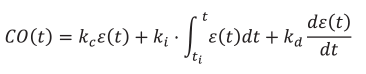
Where:
ε=PV-SP is the control error for a direct acting controller.
ε=SP-PV is the controll error for a reverse acting controller.
C0 is the controller output.
kc is the controller proportional gain (dimensionless).
ki is the controller integral gain (reciprocal of time, for example per second, per minute, or per hour). Note that some vendors refer to the units for this parameter as repeats per minute drawing on the behavior of the controller for a constant error.
kd is the controller derivative gain (time unit, for example seconds, minutes, or hours).
ti is the time at the last initialization of the integrator, for example when the controller was last in manual.
Standard. Gain adjustment applied to proportional, integral, and derivative terms to form controller output. 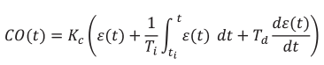
Where:
ε=SP-PV is the control error for a direct acting controller.
ε=SP-PV is the control error for a reverse acting controller.
Ti is the controller integral action time (time units for example seconds, minutes, or hours).
Td is the controller derivative action time (time units for example seconds, minutes, or hours).
The standard and series algorithms are close in form to that for the equivalent pneumatic controller since the gain on a pneumatic controller is adjusted by positioning the flapper pivot point, which equally affects the integral and derivative bellows.
It is important to note that the nomenclature “standard” is not meant to imply that this version of the PID controller is to be the standard, preferred, proper, or best practice. It is a conventional and frequently used form that gained widespread use through early adoption in electronic analog systems.
Series. The derivative term applied before proportional plus integral terms is represented by the following equations.
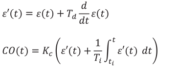
Or 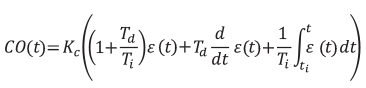
Where:
ε=PV-SP is the control error for a direct acting controller.
ε=SP-PV is the control error for a reverse acting controller.
Like the standard algorithm, gain adjustments apply to proportional, integral, and derivative terms; the derivative term is best described as a “phase advance” term acting on the error prior to it being processed by proportional and integral terms. Note that if the derivative action time, Td is zero, the series from is identical to the standard form.
Features and opportunities
PID has been proven to be the most effect algorithm for minimizing the impact of unmeasured process input disturbances (load disturbances) that have by far the most prevalent detrimental effect on loop performance. Recent advances in algorithm features have enabled the best load disturbance rejection while meeting other objectives. For example, after tuning for load response, setpoint lead-lag, or setpoint weights can enable the best setpoint response. The scheduling or adaptation of tuning settings enables PID to better handle the inevitable nonlinearities.
External-reset feedback (ERF) from the positive feedback implementation of integral action lost in the transition from pneumatic to electronic controllers has been retained by one supplier and restored by another. ERF has been recognized as having inherent capability in minimizing oscillations from unnecessary crossings of the split range point, slow valves, and slow secondary loops plus offering better override control, valve position control, and dead time compensation. ERF has also led to an enhanced PID that can handle large and variable analyzer cycle times and signal failures.

ISA Standards and Technical Reports
ISA standards help automation professionals streamline processes and improve industry safety, efficiency, and profitability. More than 150 standards reflect the expertise of more than 4,000 industry experts around the world. One of the many benefits of ISA membership is free viewing of most ISA standards and technical reports. The ISA-TR5.9-2023 Proportional-Integral-Derivative (PID) Algorithms and Performance technical report is available for purchase from ISA.
Most of the PID capability has been underutilized due to the lack of knowledge of PID algorithms and performance implications. This situation has been severely aggravated by the loss of expertise and the inconsistencies in the nomenclature and implementation most notably of the PID form. Particularly detrimental is the misconception that the PID algorithm works with signals in engineering units and that disturbances are on the process output. ISA-TR5.9 can put us all on the right track.
Reader Feedback
We want to hear from you! Please send us your comments and questions about this topic to InTechmagazine@isa.org.