

- By A.J. Cottengim, Diep Nguyen, PE, Jeff Gilman, PE, Todd Reynolds, PE
- Special Section
Summary
Fast Forward
- An online water quality and control system is an effective way to monitor and control water quality.
- SCADA system reliability is key to online data collection and calculations.
- The online water quality and control system conforms to EPA water quality surveillance and response system guidelines.

Effective method to monitor and control water quality to blend groundwater in small quantities with the surface-water supplies and conform to all regulatory drinking water standards

The San Francisco Public Utilities Commission (SFPUC), the municipal water supply agency for the city and county of San Francisco, Calif., began mixing groundwater from a local aquifer with the city's customary surface-water supply sources in April 2017. San Francisco had not used groundwater as a drinking water supply for more than 90 years. The planning, engineering design, and construction for this renewed groundwater use was accomplished under the San Francisco Groundwater Supply Project (SFGW Project), a part of the agency's capital program to diversify the city's drinking water supply sources and increase their reliability.
Due to differences in water quality between the groundwater and surface water, the SFGW Project opted to blend groundwater in small quantities with the surface-water supplies in two city reservoirs. This blending or mixing allows the city to continue to surpass all regulatory drinking water standards, as well as to ensure that changes in taste or odor are not noticed. A specialized project team developed and executed an online monitoring and control system to satisfy the project's water quality requirements. The team includes SFPUC project management staff. The team members for the water quality control system included personnel from DTN Engineers, Kennedy/Jenks Consultants, and Tesco Controls.
Background
SFPUC is a purveyor to water retail customers in the city and county of San Francisco, as well as to 26 wholesale customers that serve Alameda, San Mateo, and Santa Clara counties in the greater Bay Area. From the mid-1930s until recently, SFPUC's municipal supply came from the Hetch Hetchy Regional Water System, a system that combines the surface-water resources of the Hetch Hetchy Reservoir in the Sierra Nevada mountain range with five reservoirs in the Bay Area. On average, 85 percent of SFPUC's water has been supplied by the Hetch Hetchy Reservoir, and the five Bay Area reservoirs have provided the remaining 15 percent.
Beginning in the mid-2000s, SFPUC embarked on the Water System Improvement Program (WSIP), a $4.8-billion-dollar, multiyear capital program to upgrade SFPUC's regional and local water systems. WSIP's primary goals included:
- seismically strengthening the regional water system by rebuilding existing facilities in vulnerable areas, such as fault zones and beneath San Francisco Bay
- maintaining the high quality of the drinking water supply by rebuilding water treatment plants and constructing new water treatment facilities
- increasing the reliability of San Francisco's water supplies by adding water wells under two groundwater projects
These two groundwater projects are the SFGW Project and the Regional Groundwater Storage and Recovery Project (GSR Project). The SFGW Project is located wholly in San Francisco, while the GSR Project is located in northern San Mateo County, south of San Francisco. Both projects tap groundwater from the Westside Basin aquifer. The SFGW Project is designed to supplement the city's drinking water at all times and is the focus of this article. The GSR Project will provide groundwater during droughts or other emergencies to both wholesale customers in the project area and to San Francisco. With groundwater supplies, SFPUC's customers are less vulnerable to disrupted services, whether from a major earthquake, drought, or other future unknowns.
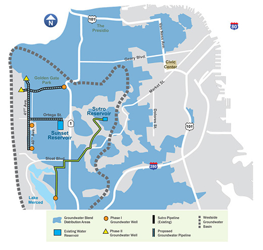
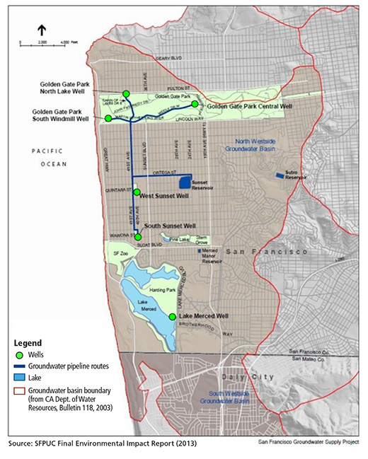
The SFGW Project consists of six groundwater well facilities, each consisting of a well and pump station, and five miles of a new groundwater transmission pipeline constructed for the project (figure 2). Five of the wells supply groundwater directly to the Sunset Reservoir via the new groundwater pipeline, where it is mixed with the Hetch Hetchy Regional Water System supply. The sixth well, located near Lake Merced, connects to the SFPUC's Lake Merced Pump Station, where the groundwater is mixed and distributed to both the Sunset and Sutro Reservoirs. In addition to mixing with the surface-water supplies, the groundwater is treated using chlorination and pH adjustment.
Four of the well facilities (phase I in figure 1) are complete and currently pumping groundwater to the Sunset and Sutro Reservoirs. The remaining two well facilities (phase II in figure 1) will begin pumping to the Sunset Reservoir by 2021. The average groundwater production will increase incrementally, with a goal of 1 million gallons per day (mgd) (1,120 acre-feet per year) during the first year and 4 mgd (4,480 acre-feet per year) when all six wells are operating. The full 4-mgd production rate represents a blend of approximately 13 percent groundwater in the Sunset Reservoir.
The quality of groundwater from the Westside Basin aquifer is different from the surface-water supplies from the Hetch Hetchy Regional Water System. The resulting groundwater-surface water blend, therefore, is also different from what customarily has been served to SFPUC customers. The key water quality variations are in general mineral content, pH, nitrate, hexavalent chromium, and manganese.
- The general mineral content of the groundwater-primarily total dissolved solids, hardness, and alkalinity-is higher than San Francisco's main supply from the Hetch Hetchy Reservoir.
- The pH of groundwater from individual wells ranges from 7.6 to 8.0 (slightly alkaline). This range is lower than the pH of SFPUC's treated surface-water supply, which is maintained at a range of 8.8 to 9.4 for optimal corrosion control. (This is required by the drinking water Lead and Copper Rule, which is enforced by the State Water Resources Control Board.)
- Nitrate and hexavalent chromium concentrations in the groundwater are higher than in the surface-water supply. Nitrate has a health-based drinking water standard (primary maximum contaminant level [MCL]). In addition, the state of California is in the process of adopting a primary MCL for hexavalent chromium, expected in 2019.
- Manganese is often found in groundwater throughout the San Francisco Bay Area at concentrations higher than the aesthetically based drinking water standard (secondary MCL). It has not, however, consistently been found above the secondary MCL in the SFGW Project wells.
As a result of the water quality differences described above, the SFGW project team developed an online water quality and control system to carefully monitor and manage the chemical treatment processes and mixing of groundwater and surface water. The major functions of this online water quality and control system are:
- monitoring individual well production rates, mechanical and electrical systems in the well facilities, and chemical treatment processes
- calculating the blended water quality in real time
- controlling the well production to ensure that the blended water quality of key regulated parameters (nitrate, hexavalent chromium, and manganese) continues to surpass the state drinking water standards
- collecting and archiving data needed for monthly regulatory reporting, to demonstrate compliance with drinking water standards
Distribution of the groundwater blend is based on the elevations and pressure zones of the Sunset and Sutro Reservoirs systems.
Control system hardware and software
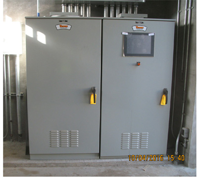
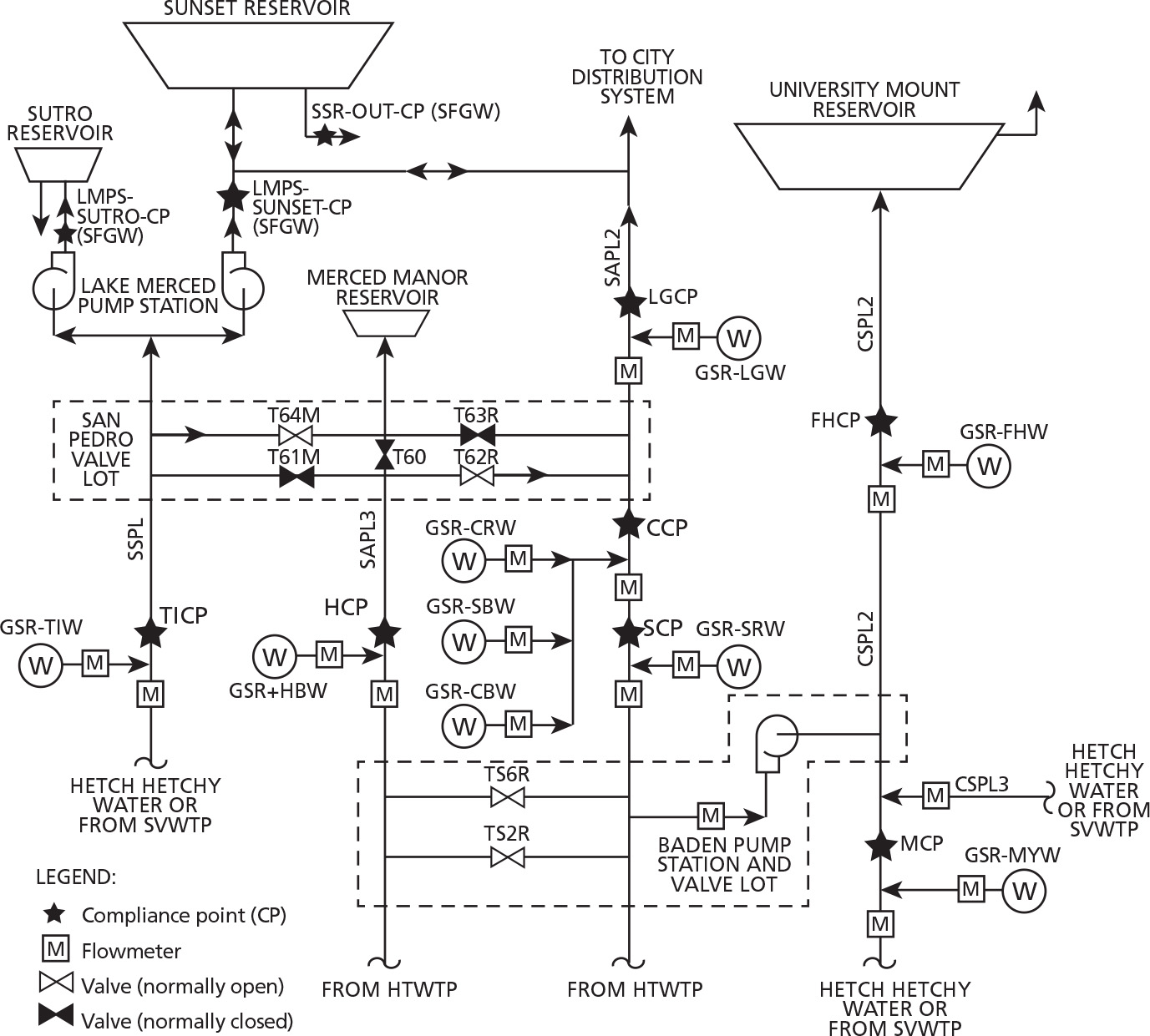
The control system for the online water quality control is a subset of the city of San Francisco's existing supervisory control and data acquisition (SCADA) system. This SCADA system is a network of computers and programmable logic controllers (PLCs) using the AT&T virtual private network (AVPN) as the main backbone (figure 3). The main controller (poll master) of the online system is at the Lake Merced facility and consists of a hot backup PLC communicating with the other main controller and remote PLCs located at each well or treatment facility. Essential signals, such as water flows, chemical flows, and water qualities (e.g., pH, chlorine), are collected at these facilities and sent to the main controller for control decisions.
The SCADA system uses Wonderware as the human-machine interface (HMI) software. The PLC uses Unity Functional Blocks with detailed annotation for each logic algorithm.
SCADA system data collection
Field instruments, such as flowmeters and water quality analyzers, continuously feed online data to the local PLC, which also monitors and controls motorized equipment such as pumps. Some of the most critical signals for the Online Water Quality Monitoring and Control System are the water flow rate signals. A flowmeter in the pipeline senses flow and generates an electrical signal back to the PLC. The PLC is then calibrated to determine what the current water flow is based on the strength of the signal.
Safety measures have been taken in the PLC to ensure that the information received from the equipment is correct. This is true for both discrete signals, such as pump run and pump fail, and analog signals, such as flows and water qualities (e.g., pH, conductivity, chlorine residuals).
Human interfacing
There are two different methods for the operators to interface with the SCADA system. First, a local operator interface (LOI) is a touchscreen associated with the site (figure 4). This screen shows a graphical representation of the equipment at the site that changes as physical inputs and outputs change. This screen also provides a location for operators to change set points and manually measured values. Any process signal associated with the online system is displayed on this LOI screen.
The second method of interaction occurs through a SCADA system with any online data displayed simultaneously on computers located at any of the four operation control centers (OCCs) on the respective computer's screen. This is the "mission control" of the water system. SCADA allows for all of the same interaction and graphical elements as the LOI, but over a much larger scale. SCADA's computing power allows it to take historical records of data for future review.
Peer-to-peer communication
One of the more difficult elements of a PLC network is maintaining proper communication between each PLC. For this reason, the Online Water Quality Monitoring and Control System uses an industry standard called a poll master. The poll master acts as a leader and initiates a conversation with each of the other PLCs. The poll master becomes a central brain having access to all information in the system. Any necessary information from one PLC is passed to the others through the poll master. If a communication failure is detected between two PLCs, alarms are immediately generated. A well site that loses communication with the poll master enters a fail-safe mode and shuts down; simultaneously an alarm is generated and sent to SCADA to inform operators, so that the corrective action can be taken.
Action by PLCs
Each individual PLC measures the water flow leaving its station. Using the flow rate (usually in gallons per minute [GPM]), the PLC can calculate the total number of gallons being supplied to the system. This flow total is then communicated to the poll master.
The poll master uses the daily flow totals from each site, as well as the set points entered by the operator at either the LOI or SCADA, to calculate the current levels of water quality. If the water quality is outside of compliance parameters, alarms are generated and sent to SCADA. The appropriate wells are automatically shut down by the poll master.
Each cycle of logic takes only about 60 milliseconds. Calculations in the PLC are checked and rechecked every cycle, meaning operators are informed of water that is not in compliance moment by moment.
Water quality objective
As aforementioned, the new groundwater source has higher hardness and naturally occurring minerals, such as iron and manganese, including the regulated constituents hexavalent chrome (chrome-6) and nitrate, than the surface water sources. The water quality objectives for the SFPUC Groundwater Program are to treat and blend the groundwater sources to meet drinking water quality regulations, and just as importantly, to maintain the high-quality and "good tasting" water to which San Francisco residents are accustomed.
Groundwater treatment approach
The groundwater quality from the 15 wells varies. Some wells do not require any treatment; some have minimal chemical conditioning systems; and some have more extensive treatment systems. For example, several well stations include filters to remove iron and manganese, and many wells add chlorine to match the disinfection residual in the imported surface water. In all cases, the relatively low flows of groundwater are blended into generally much higher flows of surface water, such that customers should not be able to notice a change in the aesthetic qualities of the water.
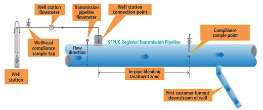
In the SFGW system, the groundwater is connected and blended directly into the large Sunset Reservoir. In the RGSR system, where groundwater is blended with treated surface water in four SFPUC transmission pipelines, the blending must take place before the water reaches the first customer on that pipeline. Figure 6 shows a schematic of the blending system configuration for a SFPUC RGSR Well Station.
The RGSR Well Station transmission pipeline blending system includes the following components:
- Well head compliance sample tap: for raw groundwater sample collection.
- Well station flowmeter: measures groundwater flow rate into the transmission pipeline.
- Transmission pipeline flowmeter: measures flow rate for blending calculations and the direction of the surface water flow in the transmission pipeline.
- Connection point to the SFRWS transmission pipeline: point on transmission pipeline where chemically treated groundwater from the well station is introduced.
- Blending treatment zone: section in the transmission pipeline where the chemically treated groundwater and the surface water are mixed. The blending zones range between 400 and 580 feet, depending on the particular conditions at the station.
- Compliance sample point: where water quality samples are monitored for compliance, located downstream of the blending zone but upstream of the first customer turnout.
- Distance to first customer turnout: a minimum of 100 feet from the compliance sample point for each well station to the first customer turnout.
System water quality monitoring and control
The water quality of the SFPUC blended water is monitored and controlled at each well station transmission line compliance point and as an overall system.
Water quality analyzers and flowmeters at each well station continuously monitor the system and calculate the blended water quality at the transmission pipeline compliance points. Some water quality parameters, such as pH and chlorine residual, can be monitored in real time with online analyzers. Some parameters, such as chrome-6 and nitrate levels, are calculated based on mass balance calculations for the system.
The SCADA system monitors and calculates the combined water quality from multiple wells that contribute to a common transmission pipeline. As the flow rates of surface water and groundwater change, the SCADA system adjusts the calculations to automatically update the calculated water quality parameters. Online analyzers for pH, conductivity, and chlorine residual also provide real-time feedback for adjustments to the well chemical feed systems. The SCADA system also generates alarms and automatically shuts down affected groundwater wells when the monitored or calculated water quality parameters exceed a predetermined set point. This ensures that the blended water quality will always meet SFPUC's water quality objectives to maintain high-quality, "good tasting" water for customers.
Preliminary functional startup tests successfully showed that the online water quality and control system operates very effectively in monitoring and controlling the water quality for the ultimate purpose of delivering high-quality drinking water to the city of San Francisco residents. Functional startup tests also prove that the highly reliable SCADA system has been the most important element of the control system that operates 24/7 with highly competent SF staff contributing to the success of this project.
Reader Feedback
We want to hear from you! Please send us your comments and questions about this topic to InTechmagazine@isa.org.