Wireless devices reduce road trips for pulp and paper mill workers.
Wireless devices reduce road trips for pulp and paper mill workers.
State regulations require pulp and paper companies to monitor and record daily effluent water rates. An employee from the main control site of a leading pulp and paper company in the Pacific Northwest went to
a remotely located pond three times a day to manually record water levels to fulfill this requirement. This process was inefficient and time-consuming, and it didn’t provide operators of the pulp and paper facility with real-time data. By installing digital and wireless technology, the company implemented a system that is scalable for future installations while reducing employee workload and maintaining state regulatory compliance.
Problem details
The pulp and paper company needed to monitor effluent water flow as it drains into a remote pond at its facility. Because of a new government regulation, personnel had to drive a truck three times a day to the remote site, log the height of the water along with the date and time, and return to the office. The company realized this was not an efficient use of time and wanted to automate the process.
This was done by calculating changes in water level in a V-neck weir entering the pond and using this data to calculate flow rate.
In addition to automating flow data collection, the company also wanted this data to be displayed on an Ethernet-based human machine interface (HMI) panel in its boiler room. Since the data was required by the state, it needed to implement a historical collection and archiving system that allowed operators to easily view historical data and produce reports when required. Seeking a quick and efficient solution, the company turned to Autoline Controls, a full-service process instrumentation manufacturer’s representative with expertise in the pulp and paper industry.
Solution
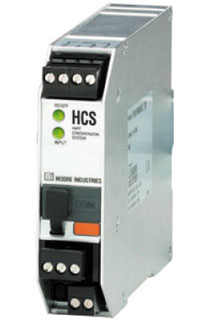
Figure 1. The HART radar level transmitter is connected to a HART concentrator system (HCS) to send weir flow level and diagnostic information to the boiler control room.
Dale Stepper at Autoline Controls first suggested implementing a system at the pond site that uses a HART radar level transmitter (Figure 1) with precise measurement capabilities and a HART concentrator system (HCS). The HCS is a HART-to-MODBUS RTU converter that serves as a HART master and polls the HART radar level transmitter to obtain its primary variable (PV) data—in this case, water flow level. In addition, the HCS receives and converts the level transmitter’s secondary variable (SV), tertiary variable (TV), and fourth variable (FV) to MODBUS RTU along with diagnostic data.
There were two main reasons why Autoline Controls chose an HCS for this solution. First, the HCS accurately gathers the digital level data from the transmitter along with giving the pulp and paper managers access to additional process variable data and critical diagnostic data about the transmitter’s health and performance. The HCS also converts this HART data directly to an industry standard MODBUS RTU format, a serial communication standard that almost all industrial radios support.
The HART radar level transmitter has a front panel display for local viewing and connects to the HCS’s input via a two-wire twisted pair cable. The radar gauge sensor measures the water height in the weir and publishes this data along with other process variable and diagnostic data to its internal HART memory location. This HART data is then polled by the HCS two to three times per second. The data is then mapped to a MODBUS memory map that resides in the HCS. This constant polling process ensures that data is continually updated on both the HART and MODBUS sides of the HCS.
Using the HART radar transmitter connected to the HCS solved the problem of measuring the water level; the next step was transmitting this data to site operators. In this case, the data needed to go to an Ethernet-based host HMI panel and a historical collection system. There were no Ethernet networks, fiber lines, or twisted pair wires available from the pond site to the control room, so installing a local wireless network was chosen as the best method for acquiring these signals.
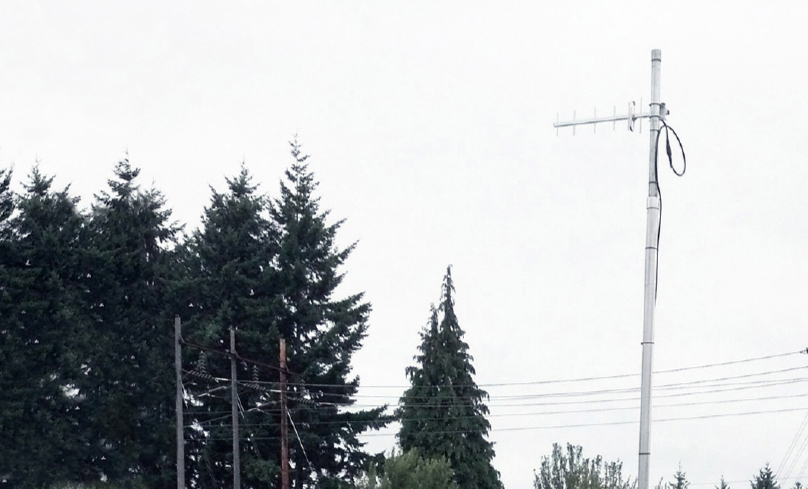
Figure 2. The omnidirectional antenna situated on the boiler room rooftop offers complete radio signal coverage for the entire site.
An initial wireless site survey done using photos of the site showed potential problems in establishing a direct line of communications from the field site to the host system due to either tree growth in the forest or accumulated snow on tree branches that may diminish the wireless radio’s signal strength. Since there was potential for future RF signal path attenuation, Autoline Controls recommended the following wireless components:
Wireless network module (WNM) radios from Moore Industries were used. Frequency hopping spread spectrum (FHSS) 900 MHz radios were used instead of 2.4 GHz models as their longer signal wave-length tends to better penetrate foliage.
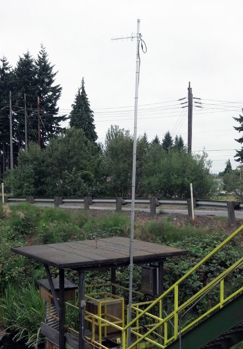
Figure 3. The Yagi-directional antenna was used at the pond site to transmit level signals from the HART level transmitter to the boiler room.
Ethernet versions of WNM radios were installed to meet the customer’s existing preference to use Ethernet communications throughout the facility. While the remote pond site previously had no communications links, using Ethernet communications at the pond site is a desirable forward step in extending the ability to add future assets with minimum added investment.
The 900 MHz Yagi antennas were installed at both the boiler site (Figure 2) and at the pond site (Figure 3) with the narrow RF beams directed toward each other. After this was proven to be successful, the boiler site antenna was changed to an omnidirectional antenna to enable expansion of the boiler site to communicate via wireless Ethernet with all locations of the facility.
Low-loss coax antenna cables with lightning arrestors were used.
The last piece of the solution involved delivering the level transmitter’s signals to their host system in a manner that met their total requirements. The site operators expressed a desire for the level transmitter’s data to be represented by both digital and analog signals.
While this could get quite expensive with traditional programmable logic controller (PLC) or distributed control system (DCS) solutions, Autoline Controls recommended adding a small net concentrator system (NCS) to the host site. The NCS is a dynamic input/ output (I/O) system that can act as an expandable I/O system, MODBUS RTU master, MODBUS RTU slave, or MODBUS/TCP slave. The NCS also provides myriad math and logic solutions through its embedded control and logic program.
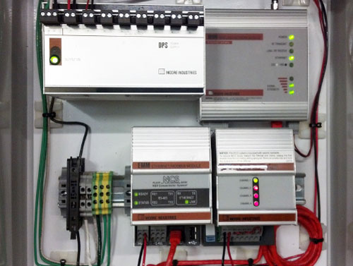
The heart of the NCS system is the Ethernet/MODBUS module (EMM), which is the NCS’s CPU and communications center (Figure 4). The EMM takes on various roles in this application. It first acts as the MODBUS RTU master and polls the HCS at the pond site through the serial port of the WNM radio. The MODBUS RTU data collected from the HCS contains the HART data from the level transmitter and is then placed into the EMM’s local memory map. Here it is stored as MODBUS RTU and MODBUS/TCP compliant registers. Figure 4. The wireless receiving panel installed at the boiler room of the pulp and paper mill. An Ethernet/MODBUS interface module (EMM) of the NCS serves as a MODBUS master to retrieve HART data from the HCS at the pond site.
The EMM is polled as a MODBUS/TCP slave by the Ethernet-based HMI at the boiler room so that site operations can view the level and diagnostic data. The EMM is then programmed with ISaGRAF logic to assign process variables to the NCS’s analog output module (AOM). The AOM provides up to four 4-20 mA or voltage signals (ranging from 0 to 10 V) that can be taken to any analog receiving device, such as a historical data collection system.
Site operations also requested that a full-time communication link with the pond site be established and verified. A simple communication watchdog routine residing in the EMM was written to monitor the wireless connection and instruct the MODBUS RTU, MODBUS/TCP, and 4-20 mA values from the AOM to go to predefined limits if there is a wireless link failure to the EMM. This allows site operations at the boiler room to immediately tell when the wireless communication link has failed. Once the link is re-established, the system automatically picks up where it left off, transmitting and making available real-time process variable and diagnostic data from the level transmitter.
End results
Autoline Controls expedited the installation. Moore Industries application engineers preconfigured the electronics and bench tested the solution using a similar radar level transmitter kept at its headquarters for such customer applications. This allowed Autoline Controls to install the system quickly and have confidence that it would work with minimal adjustments needed. The system is now enabling the pulp and paper company to efficiently get accurate and required readings on the levels of their effluent water system (Figure 5). Figure 5. HART flow level measurements at the pond site are converted to MODBUS RTU by an HCS and sent from a WNM at the pond to a receiver radio at the boiler control room. The information is relayed from the wireless radio to an HMI display and DCS/historian by the NCS.
“Part of their license with the state required them to send an employee to the site to write down numbers three times a day, seven days a week,” Stepper said. “That’s essentially one-half of the work of a full-time employee—including having to work weekends. This system automates their formal measurement and documentation requirement process, and lets their employees focus on other critical aspects of their operation.”
NOTE: This article is compiled from information provided by Moore Industries.
Images courtesy of Moore Industries
Reader Feedback
We want to hear from you! Please send us your comments and questions about this topic to InTechmagazine@isa.org.